
1-805-484-2992
Quotes - Engineering - SalesRefrigerated Air Dryers for Dairy Processing
A dairy is the most actuator-dense plant in the food industry. A mid-size fluid milk plant has several hundred pneumatic actuators on its mix-proof valve clusters, and every one of them opens and closes dozens of times a day through production and CIP. Around them are the fillers for cartons and jugs, the blow molder that makes the HDPE jugs with 90 to 125 psig air inside the bottle, the cheese vats and churns, the membrane plant's valves, the spray dryer's atomizing nozzles and bag-house pulse-jets on the powder side, and the instrument loops on the pasteurizer. Water in that air corrodes actuator springs and pilots, sticks the solenoid pilots in a valve cluster so a valve fails to seat during CIP, spits from a spray dryer nozzle, and where the air is inside a jug or a nozzle, carries whatever grew in the wet pipe into the milk.
The process hall at 50 to 60°F is served by a refrigerated dryer holding a 38°F pressure dew point, ISO 8573-1 class 4, with coalescing filtration. The cold rooms at 35 to 38°F and the product-contact points are not: those branches take a desiccant stage fed by the refrigerated dryer, and the contact points end in a sterile filter, which is what the sanitary standards for product-contact air ask for.
A fluid milk plant runs on a 75 to 150 hp screw, 320 to 700 SCFM, and a large dairy with a powder plant on 200 hp and more, often oil-free. A 100 hp screw at 450 SCFM is the 500 SCFM dryer in a normal compressor room and the 600 size in a hot one; the desiccant stage on the cold-room and contact branches is sized for those branches alone.
Dairies run seven days with the load swinging between production and CIP, and the FLXA cycling series or the AES and VDR digital-scroll and variable-speed dryers follow that swing; a plant that runs flat out around the clock is the non-cycling DXR case.
Request a dairy air dryer quote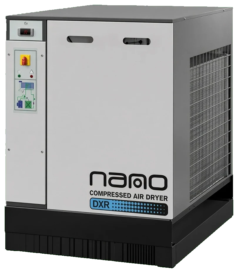
What water does in a dairy
Valve clusters, CIP and the product
- Actuator springs and pilots corroding, then a valve failing to seat during CIP
- Solenoid pilots in valve clusters sticking as condensate washes out the lubricant
- Cold-room lines condensing 38°F air in a 36°F store and flooding the actuators there
- Organisms from a wet pipe reaching the milk through jug blow air and spray dryer nozzles
The air specification for a dairy
Process hall, cold rooms and contact points
- Process hall air, class 2.4.2: 38°F pressure dew point from a refrigerated dryer with a 0.01 micron coalescer
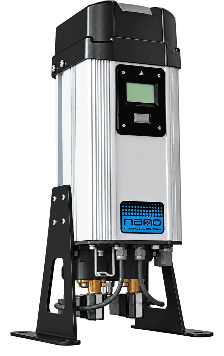
- Cold-room branches through a desiccant stage fed by the refrigerated dryer, because the rooms sit below 38°F
- Contact points, class 2.2.1: desiccant air, oil to 0.01 mg per cubic meter, sterile filter at the nozzle or blow pin
- Zero-loss drains at every low point, since a seven-day plant cannot afford timer drains venting all year
Dryers that fit a dairy
Capacities at 100 psig with 100°F inlet air. A fluid milk plant on a 75 to 150 hp screw uses the 400 to 700 SCFM sizes; a dairy with a powder plant uses 850 to 1,250 SCFM and beyond, where the AES and VDR series track the swing between production and CIP.
| SERIES | TYPE | FLOW RANGE | MAX INLET | MAX PRESSURE |
| DXR Series | Non-Cycling | 10 to 4,200 SCFM | 131°F | 203 psig |
| FLXA Series | Cycling | 75 to 2,000 SCFM | 120°F | — |
| AES Series | Digital Scroll Cycling | 600 to 10,000 SCFM | 120°F | 232 psig |
| VDR Series | Variable Speed Cycling | 2,600 to 8,450 SCFM | 158°F | 203 psig |
| HF Series Filters | Compressed Air Filter | 20 to 21,250 SCFM | — | 300 psig |
| GFN Series Filters | Compressed Air Filter | 6 to 1,500 SCFM | — | 232 psig |
| ND Series Zero-Loss Drains | Condensate Drain | Call for sizing | — | 290 psig |
| PDM Dew Point Monitor | Dew Point Monitor | Call for sizing | — | 145 psig |
Send the compressor horsepower, the cold room temperatures and the product-contact points; we size the plant dryer and specify the cold-room and contact branches.
Three temperatures, one air system
A dairy's air passes through three climates. It is made in a compressor room that runs 100 to 115°F beside the ammonia plant, it is used in a process hall at 50 to 60°F, and part of it goes into cold rooms at 35 to 38°F. A refrigerated dryer rated at 100°F ambient loses capacity in the first, is comfortably dry in the second and is below its dew point in the third.
The layout that respects all three is a dryer sized with the ambient correction or water-cooled, a header that stays in the warm hall with cluster drops from the top, and a desiccant branch for the cold rooms and the contact points. Anything simpler puts water in an actuator somewhere.
- Dryer sized for the compressor room's summer temperature, or water-cooled
- Header routed through warm space, drops from the top
- Desiccant branch for every room below 38°F and every contact point
Where the dryer and filters go
Compressor, aftercooler, receiver, 1 micron prefilter, refrigerated dryer, 0.01 micron coalescer, header, then stainless drops to each valve cluster with a filter-regulator at the panel. The cold-room branches and the contact branches leave the header through a desiccant dryer sized for them, and each contact point ends in a sterile filter at the blow pin or the nozzle. The dryer lives in the compressor room, which in a dairy is often next to the ammonia plant and hot; the ambient conditions page gives the correction, and the FLXA and AES series come water-cooled where the room runs above 105°F.
Valve clusters and CIP
A mix-proof valve that fails to seat during CIP is a cross-contamination event, and the usual cause is a sticking pilot valve or a corroded actuator spring fed with wet air. Dry the header at the compressor room, take every cluster drop off the top of the pipe, and put a drain leg at the end of each run so the actuators never see liquid. The piping and bypass page shows the drop and drain-leg details.
Cycling or non-cycling for a dairy
A dairy's air load is production by day, CIP in blocks and a quieter night with the compressor holding pressure for the clusters. That swing is what the FLXA cycling series and, above 600 SCFM, the AES digital-scroll and VDR variable-speed dryers are built for: refrigeration follows the load instead of running flat out through the CIP lull. A plant that runs flat out around the clock, which large fluid milk plants do in season, is served more simply by the non-cycling DXR. The cycling versus non-cycling page works the payback for a seven-day plant.
Jug blow molding and spray dryers
The extrusion blow molder that makes HDPE jugs blows 90 to 125 psig air inside the bottle that the milk goes into a few minutes later, and a spray dryer's two-fluid nozzles atomize concentrate with compressed air. Both are contact air: a –40°F dew point from the desiccant branch, oil to 0.01 mg per cubic meter and a sterile filter at the blow pin or the nozzle manifold. On a lubricated compressor, the activated carbon stage on the plant header keeps oil vapor out of both.
Dairy plant air questions
Because the cold room is at 36°F and the air's dew point is 38°F, so the line condenses inside the room and every actuator on it gets water. Feed cold-room branches from a desiccant stage after the refrigerated dryer, or route them through the warm hall and drop in from above with a drain leg at the door.
No. Oil-free air is saturated with water at the aftercooler outlet like any other, and the refrigerated dryer, separator, coalescer and drains stay the same. What changes is that the activated carbon stage becomes optional, because there is no oil vapor for it to catch.
The blow air inside an HDPE jug, spray dryer atomizing air, pulse-jet air in a powder bag house, and any blow-down or purge that enters a tank or a filler bowl. Valve actuators, CIP manifolds, fillers' cylinders and instruments are non-contact and stay on the refrigerated dryer at class 2.4.2.
A 100 hp screw delivers 430 to 460 SCFM, which is the 500 SCFM dryer at a normal compressor room temperature and the 600 SCFM size in a 110°F room beside the refrigeration plant. If the load swings between production and CIP, the FLXA cycling series in that size; if the plant runs flat out, the DXR.
The receiver handles the peak; the dryer handles the compressor's output. A CIP sequence that fires fifty actuators in a few seconds draws from the receiver, which the compressor refills at its rated flow through the dryer. Size the receiver at three to five gallons per SCFM and the dryer for the compressor.
More on dairy plant air
Dryers for 60 to 250 hp screw compressors
The compressor class most dairies run, matched to the 300 to 1,250 SCFM dryer band that fits it.
Learn More
Food Packaging
Compressed air drying for form-fill-seal, tray sealing and reject blasts: contact and non-contact classes, chilled halls and dryer sizes.
Learn More
Bottling & Canning
Compressed air drying for fillers, cappers, seamers and rinsers: machine air at 38 degrees, rinser air with a sterile filter, hot halls.
Learn More