
1-805-484-2992
Quotes - Engineering - SalesNon-Cycling Refrigerated Air Dryers, 300 to 1,250 SCFM
Central-plant dryers for 60 to 250 hp rotary screw compressors
A 60 hp screw compressor delivers about 270 SCFM and a 250 hp machine about 1,100, so this band covers the single large compressor and the two-compressor room alike: a 100 hp duty unit with a 75 hp backup, or two 125 hp machines sharing one header through one dryer. The dryer is sized to the compressors that can run together, at 100 psig and 100°F, and then corrected for the room.
Compressors of this size are bought to run, and a plant that keeps them loaded 16 to 24 hours a day is the natural home of a non-cycling dryer. The refrigeration circuit is on whenever the dryer is on, the hot-gas bypass valve holds the evaporator at its set point through the load swings, and the 38°F pressure dew point does not wander while the sequencer shuffles compressors.
Seven current direct-expansion sizes cover 325 to 1,250 SCFM, all on 460 V three phase with 575 V available from 850 SCFM up, on 2 in and 2-1/2 in FNPT to 600 SCFM and 3 in MNPT above. The previous generation, 300 to 1,200 SCFM with 2 in NPT and 3 in and 4 in flanges, stays in the table for cross-reference.
- Rated 300 to 1,250 SCFM at 100 psig, 100°F inlet and 100°F ambient
- 460/3/60 power, 2.3 to 6.7 kW absorbed; 575 V optional from 850 SCFM
- 140°F inlet allowance on the 325 SCFM and larger current models
- Hot-gas bypass holds the dew point steady as compressors load and unload
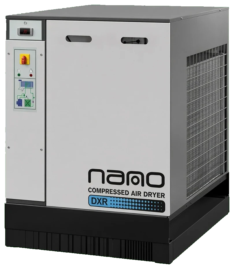
Every 300 to 1,250 SCFM non-cycling model
Capacities at 100 psig, 100°F inlet and 100°F ambient, with the connection and voltage of each unit. Part numbers link to their own pages; the current line comes first, the earlier plant-air series after it.
| PART NUMBER | SERIES | SCFM | CONNECTION | VOLTAGE | STATUS |
| DXR 0325 NA | DXR Series | 325 | 2 in FNPT | 460/3/60 | Current |
| DXR 0400 NA | DXR Series | 400 | 2 in FNPT | 460/3/60 | Current |
| DXR 0500 NA | DXR Series | 500 | 2-1/2 in FNPT | 460/3/60 | Current |
| DXR 0600 NA | DXR Series | 600 | 2-1/2 in FNPT | 460/3/60 | Current |
| DXR 0850 NA | DXR Series | 850 | 3 in MNPT | 460/3/60 (575/3/60 optional) | Current |
| DXR 1050 NA | DXR Series | 1,050 | 3 in MNPT | 460/3/60 (575/3/60 optional) | Current |
| DXR 1250 NA | DXR Series | 1,250 | 3 in MNPT | 460/3/60 (575/3/60 optional) | Current |
| HPRN300-4 | HPRN Series | 300 | 2 in NPT | 460/3/60 | Legacy |
| HPRN400-4 | HPRN Series | 400 | 2 in NPT | 460/3/60 | Legacy |
| HPRN500-4 | HPRN Series | 500 | 2 in NPT | 460/3/60 | Legacy |
| HPRN600 | HPRN Series | 600 | 2 in NPT | 460/3/60 | Legacy |
| HPRN800 | HPRN Series | 800 | 3 in flange | 460/3/60 | Legacy |
| HPRN1000 | HPRN Series | 1,000 | 4 in flange | 460/3/60 | Legacy |
| HPRN1200 | HPRN Series | 1,200 | 4 in flange | 460/3/60 | Legacy |
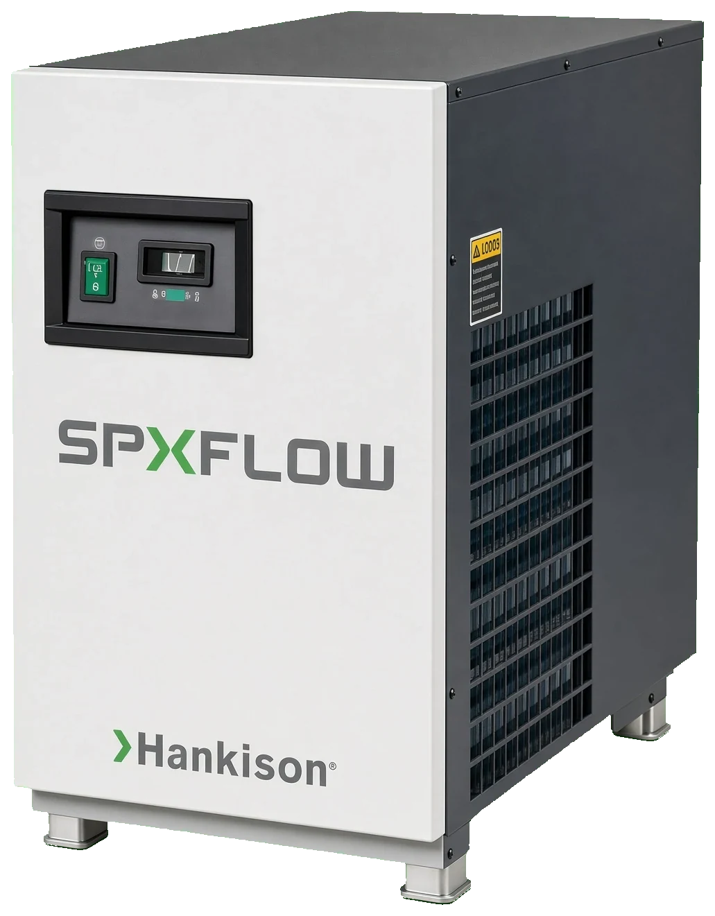
Series covering 300 to 1,250 SCFM
Sizing for one compressor or two
At 4.3 to 4.6 SCFM per horsepower a 75 hp screw is a 325 to 345 SCFM duty, a 100 hp is 430 to 460, a 150 hp is 650 to 690 and a 200 hp is 860 to 920. Where two machines can run at once the dryer is sized for the pair; where the second machine is a standby that never runs with the first, it is sized for the larger of the two. One dryer on a common header is simpler and cheaper than one per compressor, but it also means one bypass and one set of filters carry the whole plant, which argues for a full-flow bypass and spare elements on the shelf.
Inlet temperature and the compressor room
Larger screw compressors reject a great deal of heat, and a compressor room without ducted exhaust can climb to 110°F in summer while the aftercooler discharges at 125°F. The 140°F inlet allowance on the current 325 SCFM and larger models keeps the dryer operating, but at 120°F inlet its capacity is roughly 65 percent of nameplate, so a 400 SCFM compressor in that room needs the 600 SCFM dryer. Ducting the compressor exhaust outdoors is usually cheaper than the two dryer sizes it saves.
Exchanger, drain and controls
The current line uses one aluminum block that precools, chills and separates in a single pass, so pressure drop stays low for the 3 to 6 kW these units absorb. Condensate leaves through a zero-air-loss drain that opens on level rather than on a timer, which at 1,000 SCFM saves a measurable amount of compressed air over a year. A digital dew point display on the panel gives the operator a number to log each shift. The previous generation used stainless plate exchangers, a timed electric drain and an LED display with a dry-air alarm contact.
Non-cycling or cycling at this size
The decision turns on hours loaded. A 600 SCFM non-cycling dryer absorbs about 4 kW around the clock, roughly 35,000 kWh a year; a cycling dryer of the same capacity may use half that in a plant that idles nights and weekends, and about the same in a plant that does not. Three-shift bottlers and continuous process plants stay with non-cycling for its simplicity and lower first cost. The cycling versus non-cycling page works the arithmetic, and the cycling models in this band are the alternative.
300 to 1,250 SCFM dryer questions
A 100 hp screw delivers 430 to 460 SCFM at 100 to 125 psig, which points at the 500 SCFM model in a normal compressor room. If the room runs above 100°F in summer or the aftercooler discharges hotter than 110°F, step up to the 600 SCFM size.
Yes, and it is the usual arrangement. Size the dryer for the compressors that can run at the same time, pipe it after the common receiver, and fit a full-flow bypass so the plant can keep running while the dryer is serviced.
The current line is threaded throughout the band: 2 in and 2-1/2 in FNPT through 600 SCFM and 3 in MNPT from 850 to 1,250 SCFM. The previous generation moved to 3 in and 4 in flanges above 600 SCFM, so a replacement may need flange adapters.
Yes, as an option on the current 850, 1,050 and 1,250 SCFM models; the standard supply is 460 V three phase. The smaller units in the band are 460 V only.
About 6 kW absorbed, which in continuous operation is close to 50,000 kWh a year. A cycling dryer of the same size would cut that in a plant with long idle periods, but in a plant loaded around the clock the two run about the same.
Leave at least 3 ft on the air inlet and discharge faces so the condenser draws room air rather than its own exhaust. Recirculated condenser air raises the condensing temperature, cuts capacity and trips the high-pressure switch on the hottest afternoons.