
1-805-484-2992
Quotes - Engineering - Sales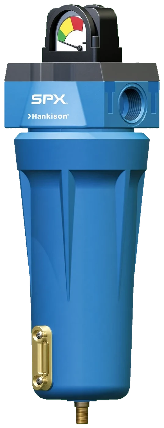
HF Grade 11 Moisture Separators
| PRODUCT | TYPE | FLOW | RATING |
|---|---|---|---|
| Moisture Separator | Impaction, 10 micron | 20 to 21,250 SCFM | 300 psig / 150°F |
Specifications
Configuration & Size
Housings:
12 to 48 modular, 54 to 92 ASME vessels (no 52)
Connections:
3/8 in NPT to 3 in NPT, 4 to 10 in ANSI flange
Element:
E11-(housing) through size 54; E11-PV in the vessels
Stocked options:
-DL drain and level window on 12 to 28, -L on 32 and 36, drain plug above
Features
- Stainless orifice tubes turn the airstream hard twice; liquid and grit carry straight on into the bowl
- About 95 percent of bulk liquid and solids to 10 micron removed, with no media to wet out
- Pressure drop holds steady for years; the element is replaced when grit builds up, not when it blinds
- Same bayonet head-to-bowl connection and push-on element as every other HF grade
Impaction separation in a filter housing
Direction changes do the work; nothing loads up
The HF Grade 11 separator is the HF filter housing fitted with an impaction element instead of a coalescing one. Two stainless orifice tubes force the air through sharp changes of direction; water droplets and solids down to about 10 microns cannot follow the turns, hit the walls and drop into the bowl, taking roughly 95 percent of the liquid with them. There is no fibrous media to saturate, so the pressure drop does not climb as the separator does its job. It goes in after the aftercooler or receiver and ahead of the dryer, and it shares housings, connection codes, options and wall brackets with the HF filters, from a 20 SCFM bowl to a 21,250 SCFM vessel.
Where it sits and what it protects. Takes the slug of water off the aftercooler so the dryer separator and the 1 micron prefilter see mist, not puddles; Sizes 12 to 28 stocked with the internal automatic drain and liquid level window, 32 and 36 with the window; Where there is no separator at all upstream, the Grade 9 separator and 3 micron coalescer in one housing is the alternative; Wall bracket kits for housings 12 through 48 hang it beside the dryer on the same bracket as the filters.
Sized close to the actual flow. A 250 SCFM dryer takes HF11-32-8-L or HF11-32-12-L; a 780 SCFM plant takes HF11-48-20 with a drain added; A separator two sizes too large runs the orifice tubes below their design velocity and lets water through at light load; Replacement element E11-32 for the example above, E11-PV packs in the ASME vessels.
Impaction works at velocity; one housing at or just above the dryer flow, never two sizes up
Request a QuoteHF Grade 11 Separators Part Numbers
| Part Number | SCFM | Connection | Notes |
|---|---|---|---|
| HF11-12-3-DL | 20 | 3/8 in NPT | Auto drain, level indicator |
| HF11-12-4-DL | 20 | 1/2 in NPT | Auto drain, level indicator |
| HF11-16-3-DL | 35 | 3/8 in NPT | Auto drain, level indicator |
| HF11-16-4-DL | 35 | 1/2 in NPT | Auto drain, level indicator |
| HF11-20-3-DL | 60 | 3/8 in NPT | Auto drain, level indicator |
| HF11-20-4-DL | 60 | 1/2 in NPT | Auto drain, level indicator |
| HF11-24-6-DL | 100 | 3/4 in NPT | Auto drain, level indicator |
| HF11-24-8-DL | 100 | 1 in NPT | Auto drain, level indicator |
| HF11-28-6-DL | 170 | 3/4 in NPT | Auto drain, level indicator |
| HF11-28-8-DL | 170 | 1 in NPT | Auto drain, level indicator |
| HF11-32-8-L | 250 | 1 in NPT | Level indicator |
| HF11-32-12-L | 250 | 1-1/2 in NPT | Level indicator |
| HF11-36-8-L | 375 | 1 in NPT | Level indicator |
| HF11-36-12-L | 375 | 1-1/2 in NPT | Level indicator |
| HF11-40-16 | 485 | 2 in NPT | |
| HF11-40-20 | 485 | 2-1/2 in NPT | |
| HF11-44-20 | 625 | 2-1/2 in NPT | |
| HF11-48-20 | 780 | 2-1/2 in NPT | |
| HF11-54-24 | 1,000 | 3 in NPT | ASME vessel 225 psig |
| HF11-56-24 | 1,250 | 3 in NPT | ASME vessel 225 psig |
| HF11-60-24 | 1,875 | 3 in NPT | ASME vessel 225 psig |
| HF11-64-4F | 2,500 | 4 in ANSI flange | ASME vessel 225 psig |
| HF11-68-4F | 3,125 | 4 in ANSI flange | ASME vessel 225 psig |
| HF11-72-6F | 5,000 | 6 in ANSI flange | ASME vessel 225 psig |
| HF11-76-6F | 6,875 | 6 in ANSI flange | ASME vessel 225 psig |
| HF11-80-6F | 8,750 | 6 in ANSI flange | ASME vessel 225 psig |
| HF11-84-8F | 11,875 | 8 in ANSI flange | ASME vessel 225 psig |
| HF11-88-8F | 16,250 | 8 in ANSI flange | ASME vessel 225 psig |
| HF11-92-10F | 21,250 | 10 in ANSI flange | ASME vessel 225 psig |
Flows are at 100 psig inlet; the connection code is the pipe size in eighths of an inch (8 = 1 in, 24 = 3 in) with F for an ANSI flange, and sizes 40 and up ship with a drain plug, so add the D internal drain or an external zero-loss drain on the X adapter.
HF Grade 11 Separators Applications


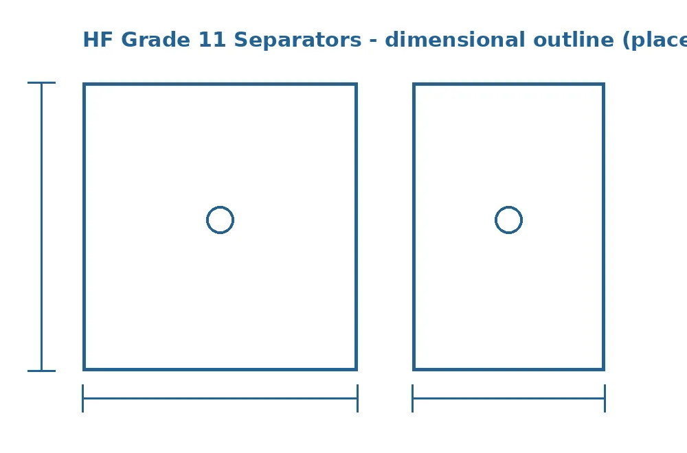
Dimensions and mounting
Same outline as the HF filter of the same housing number.
The separator mounts upright with the ports in line through the head and the bowl below, in a straight run as close to the aftercooler outlet as the pipe allows. The flow arrow on the head must be followed: the orifice tubes are directional, and a reversed housing separates almost nothing. Leave clearance under the bowl equal to the bowl length plus the element length; the element is changed far less often than a coalescer, but the bowl still has to come off to clean out grit, and a housing pinned against a receiver cannot be opened.
This bowl collects more liquid than any filter downstream, so the drain is the critical fitting. On sizes 12 to 28 the internal automatic drain discharges from the bottom of the bowl; pipe it to a condensate line. On sizes 40 and up, which ship with a drain plug, fit the D option or an external zero-loss drain, because a separator that is never drained fills its bowl and passes water on to the dryer. The ASME vessels from size 54 stand on the floor with flanged side connections, and the vessel drawing gives the pull clearance for the element pack.
The outline above is a modular housing; confirm the size, the connection code and the drain arrangement, and the vessel drawing for sizes 54 and up, with the quote.
Common FAQs
20 to 21,250 SCFM
- Housings: 12 to 48 modular, 54 to 92 ASME vessels (no 52)
- Connections: 3/8 in NPT to 3 in NPT, 4 to 10 in ANSI flange
- Element: E11-(housing) through size 54; E11-PV in the vessels
- Stocked options: -DL drain and level window on 12 to 28, -L on 32 and 36, drain plug above
- Max pressure: 300 psig with drain plug, 250 psig with auto drain
- ASME vessels: 225 psig, sizes 54 to 92
- Temperature: 35 to 150°F
- Separation: 10 micron mechanical, about 95 percent of liquid
- Housing finish: Chromated and epoxy powder coated inside and out