
1-805-484-2992
Quotes - Engineering - Sales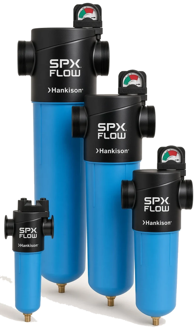
NGF Series Compressed Air Filters
| PRODUCT | GRADES | FLOW | RATING |
|---|---|---|---|
| Threaded Inline Filter | SF, PF, HF, UF, CF | 20 to 1,500 SCFM | 250 psig / 150°F |
Specifications
Configuration & Size
Housings:
02, 03, 04, 06, 07, 08, 10, 11, 12, 13, 14, 15, 16, 17
Connections:
1/4 in NPT (02) through 3 in NPT (16, 17)
Elements:
(grade)-(housing), for example PF-07 or HF-07
Stocked options:
D float drain and P1 or G1 indicator; W external drain on 14 to 17
Features
- SF: 3 micron separator filter for bulk liquid, 5 mg/m3 oil, where there is no separator ahead of it
- PF: 1 micron particulate and coalescing prefilter, 2 mg/m3 oil, the element that protects the dryer
- HF: 0.01 micron coalescer at 99.999 percent, under 0.01 mg/m3 oil, the afterfilter for tools, controls and paint
- UF and CF: 0.001 mg/m3 liquid oil, then activated carbon for vapor and odor in food and pharmaceutical air
Five grades, color coded on the end cap
SF and PF do the coarse work, HF and UF the oil, CF the vapor
The NGF Series is the threaded inline filter that ships as the filter pack on refrigerated dryers ordered with the -FP suffix. Fourteen die-cast aluminum housings, 02 through 17, cover 20 to 1,500 SCFM on 1/4 in through 3 in NPT, and each takes one of five color-coded pleated elements: SF bulk-liquid separator, PF 1 micron particulate, HF 0.01 micron oil removal, UF ultra-high-efficiency oil removal and CF activated carbon. The usual dryer pair is a PF prefilter and an HF afterfilter of the same housing size. Elements are pleated glass media on a stainless core with about half the pressure drop of a wrapped element.
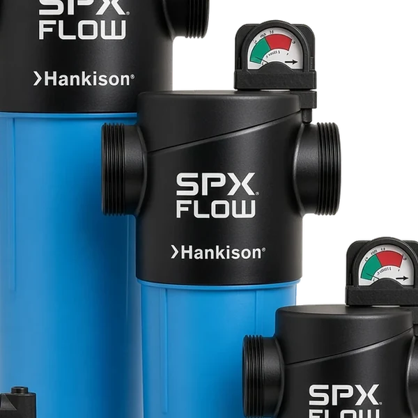
Pleated element, sculpted housing. Pleated glass media with a 96 percent open volume on a stainless support core; Large flow paths cast into the head; chromated and epoxy powder coated inside and out; An audible warning sounds if the bowl is loosened while the housing is still under pressure; Slide indicator standard on 02 to 07, two-color differential-pressure gauge standard on 08 to 17.
The dryer filter pack. A 75 SCFM dryer takes F07-PF-DP1 in and F07-HF-DP1 out; a 250 SCFM dryer takes the F10 pair on 1-1/2 in pipe; Float drain on housings 02 to 12 empties the prefilter bowl; sizes 13 to 17 take an external drain; Elements change yearly or at the red band on the gauge, PF-07 and HF-07 for the pair above.
NGF Series Filters Part Numbers
| Part Number | SCFM | Connection | Grade | Element |
|---|---|---|---|---|
| F02-SF-DP1 | 20 | 1/4 in NPT | SF | SF-02 |
| F02-PF-DP1 | 20 | 1/4 in NPT | PF | PF-02 |
| F02-HF-DP1 | 20 | 1/4 in NPT | HF | HF-02 |
| F02-UF-DP1 | 20 | 1/4 in NPT | UF | UF-02 |
| F02-CF-DP1 | 20 | 1/4 in NPT | CF | CF-02 |
| F03-SF-DP1 | 35 | 3/8 in NPT | SF | SF-03 |
| F03-PF-DP1 | 35 | 3/8 in NPT | PF | PF-03 |
| F03-HF-DP1 | 35 | 3/8 in NPT | HF | HF-03 |
| F03-UF-DP1 | 35 | 3/8 in NPT | UF | UF-03 |
| F03-CF-DP1 | 35 | 3/8 in NPT | CF | CF-03 |
| F04-SF-DP1 | 50 | 1/2 in NPT | SF | SF-04 |
| F04-PF-DP1 | 50 | 1/2 in NPT | PF | PF-04 |
| F04-HF-DP1 | 50 | 1/2 in NPT | HF | HF-04 |
| F04-UF-DP1 | 50 | 1/2 in NPT | UF | UF-04 |
| F04-CF-DP1 | 50 | 1/2 in NPT | CF | CF-04 |
| F06-SF-DP1 | 75 | 3/4 in NPT | SF | SF-06 |
| F06-PF-DP1 | 75 | 3/4 in NPT | PF | PF-06 |
| F06-HF-DP1 | 75 | 3/4 in NPT | HF | HF-06 |
| F06-UF-DP1 | 75 | 3/4 in NPT | UF | UF-06 |
| F06-CF-DP1 | 75 | 3/4 in NPT | CF | CF-06 |
| F07-SF-DP1 | 103 | 3/4 in NPT | SF | SF-07 |
| F07-PF-DP1 | 103 | 3/4 in NPT | PF | PF-07 |
| F07-HF-DP1 | 103 | 3/4 in NPT | HF | HF-07 |
| F07-UF-DP1 | 103 | 3/4 in NPT | UF | UF-07 |
| F07-CF-DP1 | 103 | 3/4 in NPT | CF | CF-07 |
| F08-SF-DG1 | 157 | 1 in NPT | SF | SF-08 |
| F08-PF-DG1 | 157 | 1 in NPT | PF | PF-08 |
| F08-HF-DG1 | 157 | 1 in NPT | HF | HF-08 |
| F08-UF-DG1 | 157 | 1 in NPT | UF | UF-08 |
| F08-CF-DG1 | 157 | 1 in NPT | CF | CF-08 |
| F10-SF-DG1 | 257 | 1-1/2 in NPT | SF | SF-10 |
| F10-PF-DG1 | 257 | 1-1/2 in NPT | PF | PF-10 |
| F10-HF-DG1 | 257 | 1-1/2 in NPT | HF | HF-10 |
| F10-UF-DG1 | 257 | 1-1/2 in NPT | UF | UF-10 |
| F10-CF-DG1 | 257 | 1-1/2 in NPT | CF | CF-10 |
| F11-SF-DG1 | 360 | 1-1/2 in NPT | SF | SF-11 |
| F11-PF-DG1 | 360 | 1-1/2 in NPT | PF | PF-11 |
| F11-HF-DG1 | 360 | 1-1/2 in NPT | HF | HF-11 |
| F11-UF-DG1 | 360 | 1-1/2 in NPT | UF | UF-11 |
| F11-CF-DG1 | 360 | 1-1/2 in NPT | CF | CF-11 |
| F12-SF-DG1 | 401 | 2 in NPT | SF | SF-12 |
| F12-PF-DG1 | 401 | 2 in NPT | PF | PF-12 |
| F12-HF-DG1 | 401 | 2 in NPT | HF | HF-12 |
| F12-UF-DG1 | 401 | 2 in NPT | UF | UF-12 |
| F12-CF-DG1 | 401 | 2 in NPT | CF | CF-12 |
| F13-SF-G1 | 568 | 2-1/2 in NPT | SF | SF-13 |
| F13-PF-G1 | 568 | 2-1/2 in NPT | PF | PF-13 |
| F13-HF-G1 | 568 | 2-1/2 in NPT | HF | HF-13 |
| F13-UF-G1 | 568 | 2-1/2 in NPT | UF | UF-13 |
| F13-CF-G1 | 568 | 2-1/2 in NPT | CF | CF-13 |
| F14-SF-G1 | 775 | 2-1/2 in NPT | SF | SF-14 |
| F14-PF-G1 | 775 | 2-1/2 in NPT | PF | PF-14 |
| F14-HF-G1 | 775 | 2-1/2 in NPT | HF | HF-14 |
| F14-UF-G1 | 775 | 2-1/2 in NPT | UF | UF-14 |
| F14-CF-G1 | 775 | 2-1/2 in NPT | CF | CF-14 |
| F15-SF-G1 | 1,030 | 2-1/2 in NPT | SF | SF-15 |
| F15-PF-G1 | 1,030 | 2-1/2 in NPT | PF | PF-15 |
| F15-HF-G1 | 1,030 | 2-1/2 in NPT | HF | HF-15 |
| F15-UF-G1 | 1,030 | 2-1/2 in NPT | UF | UF-15 |
| F15-CF-G1 | 1,030 | 2-1/2 in NPT | CF | CF-15 |
| F16-SF-G1 | 1,200 | 3 in NPT | SF | SF-16 |
| F16-PF-G1 | 1,200 | 3 in NPT | PF | PF-16 |
| F16-HF-G1 | 1,200 | 3 in NPT | HF | HF-16 |
| F16-UF-G1 | 1,200 | 3 in NPT | UF | UF-16 |
| F16-CF-G1 | 1,200 | 3 in NPT | CF | CF-16 |
| F17-SF-G1 | 1,500 | 3 in NPT | SF | SF-17 |
| F17-PF-G1 | 1,500 | 3 in NPT | PF | PF-17 |
| F17-HF-G1 | 1,500 | 3 in NPT | HF | HF-17 |
| F17-UF-G1 | 1,500 | 3 in NPT | UF | UF-17 |
| F17-CF-G1 | 1,500 | 3 in NPT | CF | CF-17 |
Flows are at 100 psig inlet; the part number reads housing, grade, options, so F07-PF-DP1 is the 103 SCFM housing with a 1 micron element, float drain and slide indicator, and its element is PF-07.
NGF Series Filters Applications




Dimensions and mounting
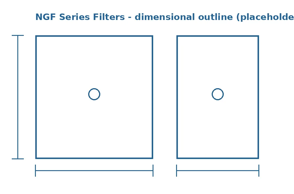
Threaded head in line with the pipe, bowl below, element out the bottom.
Every housing mounts upright with the ports in line through the head, so the filter sits in a straight run of pipe with no offset. The flow arrow on the head must point downstream: a coalescing element works from inside to outside, and a reversed housing pushes the collected oil back into the airstream. Allow clearance under the bowl for the bowl length plus the element length, because the element pulls down off the head once the bowl is unscrewed. Sizes 02 through 07 are small enough to service by hand above a bench; sizes 13 through 17 on 2-1/2 in and 3 in pipe are heavy enough that the pipe should be supported on both sides of the head.
The float drain on housings 02 to 12 discharges through a fitting at the bottom of the bowl; pipe it to a condensate line so the oil and water do not end up on the floor. Housings 13 to 17 take the external mechanical drain or a zero-loss drain on the bowl port, and the gauge on the head faces forward so the differential pressure can be read without a flashlight.
The drawing above is one threaded housing; confirm the height, port size and drain option of your housing number with the quote.
Common FAQs
20 to 1,500 SCFM
- Housings: 02, 03, 04, 06, 07, 08, 10, 11, 12, 13, 14, 15, 16, 17
- Connections: 1/4 in NPT (02) through 3 in NPT (16, 17)
- Elements: (grade)-(housing), for example PF-07 or HF-07
- Stocked options: D float drain and P1 or G1 indicator; W external drain on 14 to 17
- Max pressure: 250 psig, drain plug or internal float drain
- Temperature: 35 to 150°F
- PF grade: 1 micron, 2 mg/m3 remaining oil
- HF grade: 0.01 micron, 99.999 percent, under 0.01 mg/m3 oil
- CF grade: Activated carbon, under 0.004 mg/m3 oil vapor