
1-805-484-2992
Quotes - Engineering - Sales
FLX Series Modular Cycling Refrigerated Air Dryers
| PRODUCT | TYPE | FLOW | RATING |
|---|---|---|---|
| Refrigerated Air Dryer | Cycling, modular water-cooled skid | 3,000 to 12,000 SCFM | 225 psig / 120°F inlet |
Specifications
Configuration & Size
Systems:
3,000, 4,000, 6,000, 8,000, 10,000, 12,000 SCFM
Modules:
2 x 1,500 SCFM (3,000); 2 to 6 x 2,000 SCFM (4,000 to 12,000)
Power:
460/3/60; 14.2 to 51.0 kW
Headers:
8 in RF flange to 4,000 SCFM, 10 in to 8,000, 12 in above
Features
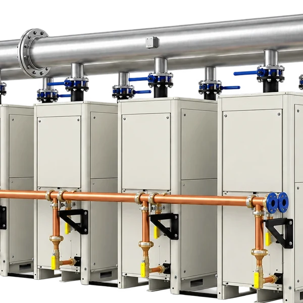
- Two to six water-cooled modules share one inlet and one outlet header on a single skid, piped and wired as one system
- Each module holds its own phase-change reservoir, so the skid cycles modules in and out to match demand from zero to 100 percent
- A module isolated for service leaves the rest of the skid on line; the plant never loses its dryer
- No-air-loss demand drains on every module
Modules on a common header
Capacity, redundancy and turndown from the same building block
The FLX Series takes the phase-change cycling dryer to central-plant scale. Each system is a skid that gangs two to six water-cooled 1,500 or 2,000 SCFM modules on a common inlet and outlet header, giving six capacities from 3,000 to 12,000 SCFM behind 8, 10 or 12 in raised-face flanges. Every module carries its own stainless steel brazed-plate three-in-one exchanger with a phase-change reservoir, so the system matches load from zero to 100 percent by cycling modules, and a module out for service leaves the rest of the skid drying air. Systems are listed by capacity: the 3,000 SCFM skid pairs two 1,500 SCFM modules, and the 4,000 to 12,000 SCFM skids stack two to six 2,000 SCFM modules.
Controls and connections at plant scale. LCD controller with a USB port and RS485 communications reports the whole skid to the plant system; 8 in raised-face flanges on the 3,000 and 4,000 SCFM skids, 10 in on 6,000 and 8,000, 12 in on 10,000 and 12,000; Water-cooled condensers keep the refrigeration heat out of the compressor room, which matters at 50 kW; With the matching filtration the skid delivers ISO 8573-1 class 1 solids and class 1 oil.
Turndown that a single big dryer cannot match. A 12,000 SCFM skid carrying a 5,000 SCFM night load has two modules cycling and four resting, drawing a fraction of the 51 kW nameplate; Redundancy is built in rather than bought twice: an N+1 arrangement is one extra module, not a second dryer; Cooling water demand follows the load as well, since a resting module rejects no heat.
FLX Series Part Numbers
| Part Number | SCFM | Connection | Voltage | Power | Dimensions (in) | Weight (lb) |
|---|---|---|---|---|---|---|
| FLX 3000 | 3,000 | 8 in RF flange | 460/3/60 | 14.2 kW | 98 x 95 x 72 | 4,204 |
| FLX 4000 | 4,000 | 8 in RF flange | 460/3/60 | 17.0 kW | 98 x 98 x 83 | 4,204 |
| FLX 6000 | 6,000 | 10 in RF flange | 460/3/60 | 25.5 kW | 100 x 148 x 83 | 7,126 |
| FLX 8000 | 8,000 | 10 in RF flange | 460/3/60 | 34.0 kW | 100 x 209.25 x 83 | 8,225 |
| FLX 10000 | 10,000 | 12 in RF flange | 460/3/60 | 42.5 kW | 100 x 258.125 x 83 | 11,438 |
| FLX 12000 | 12,000 | 12 in RF flange | 460/3/60 | 51.0 kW | 100 x 308 x 83 | 13,552 |
Capacities are at 100 psig and 100°F inlet; each system is listed by rated capacity with its module count in parentheses, and the dimensions are the assembled skid, height x width x depth.
FLX Series Applications


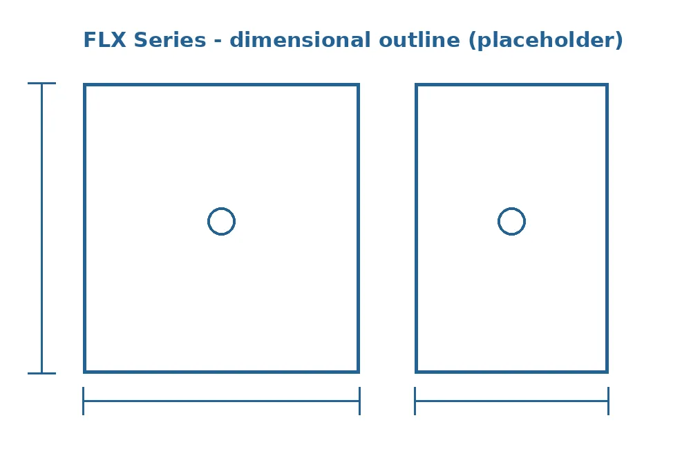
Skid dimensions, flanges and water connections
Skids grow in width as modules are added; height and depth stay close to constant.
The 3,000 SCFM skid is 98 in tall, 95 in wide and 72 in deep at 4,204 lb; the 4,000 SCFM skid with two 2,000 SCFM modules is 98 x 98 x 83 in. From there each added module extends the width: 148 in for 6,000 SCFM at 7,126 lb, 209 in for 8,000 SCFM at 8,225 lb, 258 in for 10,000 SCFM at 11,438 lb and 308 in for 12,000 SCFM at 13,552 lb, all about 100 in tall and 83 in deep. Air connections are 8 in raised-face flanges through 4,000 SCFM, 10 in through 8,000 and 12 in on the two largest.
Plan the room around the width: a 12,000 SCFM skid is 25 ft long and needs access along the service side for every module. Bring cooling water to each module with isolation valves so one can be shut off without draining the rest, and size the pad for the operating weight. The 460 V three-phase feed comes to a single point on the skid. Set the skid downstream of the receiver and the bulk separator and give it a full-line-size bypass; on a header this size the bypass valve is itself a significant piece of the piping budget.
The outline above is one module arrangement; a full skid drawing with flange heights, water connections and pad loads is issued with every FLX quote.
Common FAQs
3,000 to 12,000 SCFM
- Systems: 3,000, 4,000, 6,000, 8,000, 10,000, 12,000 SCFM
- Modules: 2 x 1,500 SCFM (3,000); 2 to 6 x 2,000 SCFM (4,000 to 12,000)
- Power: 460/3/60; 14.2 to 51.0 kW
- Headers: 8 in RF flange to 4,000 SCFM, 10 in to 8,000, 12 in above
- Inlet pressure: 75 to 225 psig
- Inlet and ambient: 80 to 120°F
- Pressure dew point: 38°F, ISO 8573-1 class 4-5
- Pressure drop: 3.9 to 4.3 psid at rated flow
- Cooling: Water-cooled condensers on every module