
1-805-484-2992
Quotes - Engineering - Sales
AXHP Series Ultra-High Pressure Refrigerated Air Dryers
| PRODUCT | TYPE | FLOW | RATING |
|---|---|---|---|
| Refrigerated Air Dryer | Ultra-High Pressure | 20 to 275 SCFM | 1,200 / 3,625 / 5,000 / 6,000 psig |
Specifications
Configuration & Size
Pressure ratings:
1,200, 3,625, 5,000 and 6,000 psig, encoded in the model number
Flows:
20, 30, 40, 60, 100, 125, 200, 275 SCFM in each rating
Power:
115/1/60 to 100 SCFM, 230/1/60 at 125, 460/3/60 at 200 and 275; 0.29 to 2.53 kW
Connections:
1/2 in NPT on every model
Features
- High-pressure stainless steel tube-in-tube heat exchanger, with every air-side component in stainless as well
- Four pressure classes, so a 1,200 psig breathing-air system and a 6,000 psig test bench each get a dryer built to its own rating
- 1/2 in NPT connections on all 32 models, the standard fitting size in high-pressure tubing systems
- Flows are rated at 100 psig reference conditions, so the tables compare directly with the rest of the site
Stainless steel from inlet to outlet
A tube-in-tube exchanger rated for the pressure class
The AXHP Series is the refrigerated dryer for compressed air and gas at pressures no ordinary dryer can touch: four pressure ratings of 1,200, 3,625, 5,000 and 6,000 psig, each offered in eight flow sizes from 20 to 275 SCFM, a matrix of 32 models. The high-pressure stainless steel tube-in-tube exchanger and all-stainless air-side components carry the pressure; the refrigeration side is a standard air-cooled R134a circuit on 115 V, 230 V or 460 V depending on flow. Every model connects with 1/2 in NPT and has a general-arrangement drawing behind it. It serves breathing-air fill stations, high-pressure test benches, gas transfer and process systems that need a 38°F dew point at line pressure.
Eight flows in each pressure class. AXHP-60-3625 is the 60 SCFM dryer rated 3,625 psig; AXHP-275-6000 is the 275 SCFM dryer rated 6,000 psig; Power draw depends only on flow: 0.29 kW at 20 SCFM, 1.05 kW at 100, 2.53 kW at 275, whatever the pressure class; 115 V single phase through 100 SCFM, 230 V at 125 SCFM, 460 V three phase at 200 and 275 SCFM; General arrangement drawings are published for every model.
Which pressure class. A 4,500 psig breathing-air cascade with a 5,000 psig relief valve takes the 5,000 psig class; a 3,000 psig system takes the 3,625 class; Flow is the free-air delivery of the high-pressure compressor: a fill-station compressor rated 45 SCFM lands on the AXHP-60; Where the pressure is under 725 psig the APET and HHPR Series are the lower-cost answer.

AXHP Series Part Numbers
| Part Number | SCFM | Connection | Voltage | Power | Dimensions (in) | Weight (lb) |
|---|---|---|---|---|---|---|
| AXHP-20-1200 | 20 | 1/2 in NPT | 115/1/60 | 0.29 kW | — | — |
| AXHP-30-1200 | 30 | 1/2 in NPT | 115/1/60 | 0.42 kW | — | — |
| AXHP-40-1200 | 40 | 1/2 in NPT | 115/1/60 | 0.57 kW | — | — |
| AXHP-60-1200 | 60 | 1/2 in NPT | 115/1/60 | 0.83 kW | — | — |
| AXHP-100-1200 | 100 | 1/2 in NPT | 115/1/60 | 1.05 kW | — | — |
| AXHP-125-1200 | 125 | 1/2 in NPT | 230/1/60 | 1.35 kW | — | — |
| AXHP-200-1200 | 200 | 1/2 in NPT | 460/3/60 | 1.99 kW | — | — |
| AXHP-275-1200 | 275 | 1/2 in NPT | 460/3/60 | 2.53 kW | — | — |
| AXHP-20-3625 | 20 | 1/2 in NPT | 115/1/60 | 0.29 kW | — | — |
| AXHP-30-3625 | 30 | 1/2 in NPT | 115/1/60 | 0.42 kW | — | — |
| AXHP-40-3625 | 40 | 1/2 in NPT | 115/1/60 | 0.57 kW | — | — |
| AXHP-60-3625 | 60 | 1/2 in NPT | 115/1/60 | 0.83 kW | — | — |
| AXHP-100-3625 | 100 | 1/2 in NPT | 115/1/60 | 1.05 kW | — | — |
| AXHP-125-3625 | 125 | 1/2 in NPT | 230/1/60 | 1.35 kW | — | — |
| AXHP-200-3625 | 200 | 1/2 in NPT | 460/3/60 | 1.99 kW | — | — |
| AXHP-275-3625 | 275 | 1/2 in NPT | 460/3/60 | 2.53 kW | — | — |
| AXHP-20-5000 | 20 | 1/2 in NPT | 115/1/60 | 0.29 kW | — | — |
| AXHP-30-5000 | 30 | 1/2 in NPT | 115/1/60 | 0.42 kW | — | — |
| AXHP-40-5000 | 40 | 1/2 in NPT | 115/1/60 | 0.57 kW | — | — |
| AXHP-60-5000 | 60 | 1/2 in NPT | 115/1/60 | 0.83 kW | — | — |
| AXHP-100-5000 | 100 | 1/2 in NPT | 115/1/60 | 1.05 kW | — | — |
| AXHP-125-5000 | 125 | 1/2 in NPT | 230/1/60 | 1.35 kW | — | — |
| AXHP-200-5000 | 200 | 1/2 in NPT | 460/3/60 | 1.99 kW | — | — |
| AXHP-275-5000 | 275 | 1/2 in NPT | 460/3/60 | 2.53 kW | — | — |
| AXHP-20-6000 | 20 | 1/2 in NPT | 115/1/60 | 0.29 kW | — | — |
| AXHP-30-6000 | 30 | 1/2 in NPT | 115/1/60 | 0.42 kW | — | — |
| AXHP-40-6000 | 40 | 1/2 in NPT | 115/1/60 | 0.57 kW | — | — |
| AXHP-60-6000 | 60 | 1/2 in NPT | 115/1/60 | 0.83 kW | — | — |
| AXHP-100-6000 | 100 | 1/2 in NPT | 115/1/60 | 1.05 kW | — | — |
| AXHP-125-6000 | 125 | 1/2 in NPT | 230/1/60 | 1.35 kW | — | — |
| AXHP-200-6000 | 200 | 1/2 in NPT | 460/3/60 | 1.99 kW | — | — |
| AXHP-275-6000 | 275 | 1/2 in NPT | 460/3/60 | 2.53 kW | — | — |
Flows are stated at 100 psig reference conditions with 100°F inlet and ambient; the second number in each model is its pressure rating in psig, and the arrangement drawing with dimensions and weight is supplied for the model quoted.
AXHP Series Applications



Arrangement drawings, connections and installation
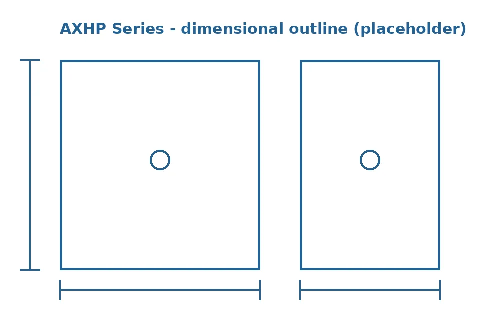
Every model carries a general-arrangement drawing; the outline here is representative.
All 32 models connect through 1/2 in NPT ports, which suits the 1/2 in and 3/8 in high-pressure tubing used on fill stations and test rigs; the fittings, isolation valves and bypass must carry the same pressure rating as the dryer, and on a 6,000 psig system that means rated cone-and-thread or high-pressure compression fittings rather than pipe-thread adapters from the hardware store. The refrigeration side is the ordinary part of the installation: a 115 V outlet through 100 SCFM, a 230 V circuit at 125 SCFM, and a 460 V three-phase feed at 200 and 275 SCFM.
Place the dryer after the compressor's final-stage separator and aftercooler with a high-pressure prefilter ahead of it, and route the drain through a high-pressure-rated drain valve to a receiver, since condensate at 5,000 psig cannot simply go to a floor drain. Keep the condenser face clear and the room between 40 and 120°F. Dimensions and weights for the model quoted are given on its arrangement drawing.
Send us the model, or the flow and pressure class, and the general-arrangement drawing comes back with the quote.
Common FAQs
20 to 275 SCFM
- Pressure ratings: 1,200, 3,625, 5,000 and 6,000 psig, encoded in the model number
- Flows: 20, 30, 40, 60, 100, 125, 200, 275 SCFM in each rating
- Power: 115/1/60 to 100 SCFM, 230/1/60 at 125, 460/3/60 at 200 and 275; 0.29 to 2.53 kW
- Connections: 1/2 in NPT on every model
- Max working pressure: 1,200 to 6,000 psig by model
- Inlet and ambient: 40 to 120°F
- Pressure dew point: 38°F
- Refrigerant: R134a
- Cooling: Air-cooled